1:开篇 在德国,每家每户都有一个信箱,家庭的电气暖账单,亲人的问候,个人的信件都会装到这个小小的箱子里。。相较于送货到人的快递,信件往往被我们所忽略,常宅在家的我,一两个星期才会检查一次信箱。虽然信件通常不重要,但检查信箱还是有点麻烦。于是,我设计了一个小小的模块,让它代替我检查信箱,每当有新的信件进入信箱,它就发送一条微信消息,提醒我取信件。
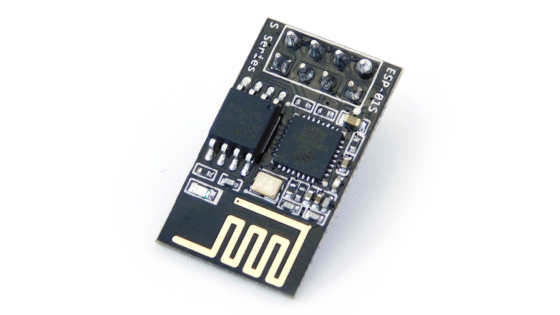
1.1 ESP8266-01 Wifi模块 wifi模块是物联网中不可或缺的一部分,通过它连上家里的wifi,向网络发送请求。调用企业微信api,来发送微信消息。
ESP8266通过串口通信与Arduino单片机通信,由3.3V直流电压供电。
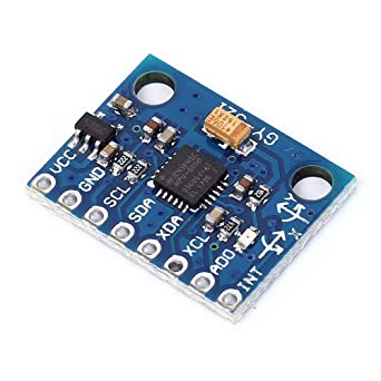
1.2 GY-521模块 GY-521指围绕MPU6050芯片所设计的电路板。
MPU6050芯片集成了加速度计、陀螺仪、温度传感器。通过i2c与Arduino单片机通信。工作电压为5V。
使用MPU6050检测信箱口的运动状态,判断是否有新的信件投入。
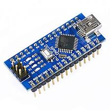
1.3 Arduino Arduino是目前非常火的开源单片机,其周边开发板大多开源,因此,一块Arduino开发板价格非常便宜,Arduino pro mini仅十块钱。我采用的是Arduino nano。其带有usb接口,比较方便调试。但是耗电会比pro mini高。
在投入使用时,考虑到电池优化,建议使用pro mini。这样整个系统的运行时长会更久。
此外,Arduino拥有庞大的社区,大部分传感器模块都有其适配支持的开源库。开发更加容易,且不用花费大量时间阅读硬件说明书。对于追求性能优化而不是仅功能实践的人来说,还是有必要阅读传感器数据手册的。
Arduino用于接收传感器的数据,并处理计算,判断是否信箱口有动作,如果有,则通过wifi模块发送微信。
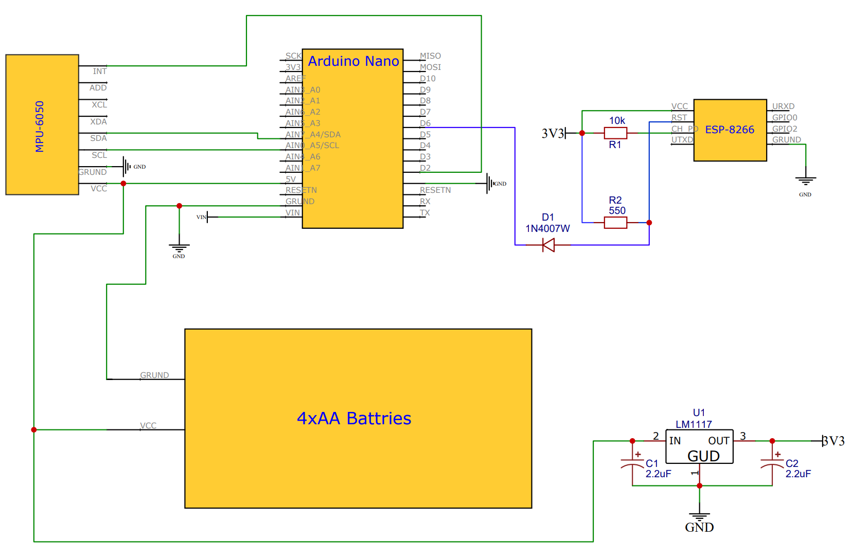
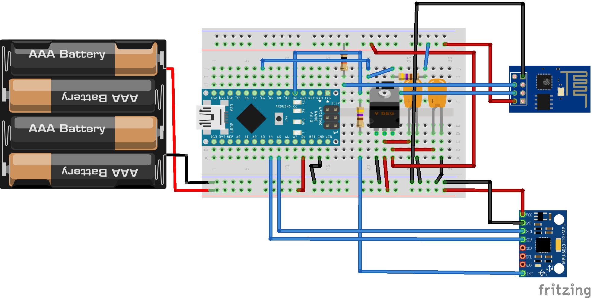
2:电路设计 这里只是简单的画了一个电路设计图,因为不需要再去制作PCB板,也就不用设计PCB板图。只要购买相应的模块,然后对照电路图连线即可。
面包板图
2.1 电源设计
通过4个AA电池串联,获得一个4x1.5V的直流电,理论电压为6V,而实际上都会小于6V。因为单片机供电要求在4.5~5.5V之间,如有必要可在电池正极接一个稳压二极管。稳压二极管由硅材料制成,其正向导通时,在PN结之间产生一个0.7V左右的压降。因此从稳压二极管输出的电压就能够满足单片机供电需求。我直接连接VCC供电是没有问题的。
当然也可以使用9~12V的电源连接VIN接口供电,或者直接使用充电宝,通过usb接口供电。需要注意的是,usb供电会额外增加电能损耗。
ESP8266模块使用3V3电源,4个干电池,无法提供3V电源,使用LM1117-3.3芯片将5V降压为3V。输入和输出口各加一个2.2uF的电容,用于稳压。
2.2 各模块接线 GY521模块SCL、SDA分别为I2C的时钟和数据总线,与ArduinoSCL和SDA相连。GY521 Int引脚接Arduino D2(INT0)引脚。
Arduino D6引脚,输出控制电平,通过一个稳压二极管,将5V高电平转3V高电平。
3:程序设计 3.1 wifi模块 当WIFI模块启动时,会发送一条微信消息。然后进入睡眠,当RST引脚接收到低电平->高电平时,WIFI模块将被唤醒。
我猜测我的WIFI模块是存在某种问题的,当它被唤醒时,并不会进行运行loop中的内容,而是进行了未知操作。因此,我在Arduino中不得不,向RST引脚发出两次低电平,第一次用于激活WIFI模块,第二次重置WIFI模块,因为它重启的时候,就会发送一条微信消息。所以也能实现既定功能。
ESP8266发送https请求时,不会自动获取服务器证书,所以需要自己从服务器去获取,可以直接从浏览器拷贝下来。这里没有使用证书,而是指纹,作用相同。
1 2 3 4 5 6 7 8 9 10 11 12 13 14 15 16 17 18 19 20 21 22 23 24 25 26 27 28 29 30 31 32 33 34 35 36 37 38 39 40 41 42 43 44 45 46 47 48 49 50 51 52 53 54 55 56 57 58 59 60 61 62 63 64 65 66 67 68 69 70 71 72 73 74 75 76 77 78 79 80 81 82 83 84 85 86 87 88 89 90 91 92 93 94 95 96 97 98 99 100 101 102 103 104 105 106 107 108 109 110 111 112 113 114 115 116 117 118 119 120 121 122 123 124 125 126 127 128 129 130 131 132 133 134 135 136 137 138 139 140 141 142 #include <Arduino.h> #include <ESP8266WiFi.h> #include <ESP8266HTTPClient.h> #include <WiFiClientSecureBearSSL.h> #include <ArduinoJson.h> #define ssid "SSIDU" #define password "Password" const char fingerprint[] PROGMEM = "790e6e32485bb89503ac6da87d948f5e634322a7" ;const int httpsPort = 443 ; String tokenUrl = "https://qyapi.weixin.qq.com/cgi-bin/gettoken" ;String sendMsgUrl = "https://qyapi.weixin.qq.com/cgi-bin/message/send?access_token=" ;String corpid = "ww98b********d" ;String corpsecret = "Kh8eKMZ**********wzQoPb0SYCqV3Tgcs" ;String agentid = "1000002" ;String get_token () String token = "123" ; String requestUrl = tokenUrl + "?corpid=" +corpid+"&corpsecret=" +corpsecret; std ::unique_ptr <BearSSL::WiFiClientSecure>client(new BearSSL::WiFiClientSecure); client->setFingerprint(fingerprint); HTTPClient https; if (https.begin (*client, requestUrl)) { Serial .print ("[HTTPS] GET...\n" ); int httpCode = https.GET(); if (httpCode > 0 ) { Serial .printf ("[HTTPS] GET... code: %d\n" , httpCode); if (httpCode == HTTP_CODE_OK || httpCode == HTTP_CODE_MOVED_PERMANENTLY) { String json = https.getString(); Serial .println (json); const size_t capacity = JSON_OBJECT_SIZE(4 ) + 290 ; DynamicJsonDocument doc (capacity) ; deserializeJson(doc, json); if (doc["errcode" ].as<int >()==0 ){ token = doc["access_token" ].as<String >(); } } } else { Serial .printf ("[HTTPS] GET... failed, error: %s\n" , https.errorToString(httpCode).c_str()); } https.end (); } else { Serial .printf ("[HTTPS] Unable to connect\n" ); } return token; } void send_msg (String msg) String token = get_token(); if (token == "123" ){ Serial .println ("not get token" ); return ; }else { Serial .println ("got token" ); } String requestUrl = sendMsgUrl + token; std ::unique_ptr <BearSSL::WiFiClientSecure>client(new BearSSL::WiFiClientSecure); client->setFingerprint(fingerprint); HTTPClient httpClient; httpClient.addHeader("Content-Type" ,"application/json" ); httpClient.begin (*client,requestUrl); String json = "{\"touser\":\"@all\",\"msgtype\":\"text\",\"agentid\":1000002,\"text\":{\"content\":\"" +msg+"\"},\"safe\":0,\"enable_id_trans\":0,\"enable_duplicate_check\":0,\"duplicate_check_interval\":1800}" ; Serial .println (json); int httpCode = httpClient.POST(json); if (httpCode > 0 ) { Serial .println ("[HTTP] POST... code:" + httpCode); if (httpCode == HTTP_CODE_OK) { Serial .println ("Send success" ); Serial .println ("return str:" +httpClient.getString()); } } else { Serial .println ("send failure" ); } httpClient.end (); } void wifi_init () WiFi .mode(WIFI_STA); WiFi .begin (ssid, password); Serial .println ("" ); Serial .println ("Connecting" ); Serial .println ("" ); while (WiFi .status() != WL_CONNECTED) { delay (500 ); Serial .print ("." ); } Serial .println ("" ); Serial .print ("Connected to " ); Serial .println (ssid); Serial .print ("IP address: " ); Serial .println (WiFi .localIP ()); } void setup () Serial .begin (9600 ); wifi_init(); } void loop () send_msg("你有一封新信件,请及时提取!" ); delay (3000 ); ESP.deepSleep(0 ); }
3.2 Arduino和GY521 在这里,Arduino会对MPU6050芯片进行初始化设置,然后进入睡眠模式。在MPU中,我们将除了Z轴加速度采样以外的所有检测模块都关闭,以提高电池的持久力。并当Z轴检测到大于阈值的运动时,产生运动中断,中断将GY521的INT引脚拉低,INT引脚连接Arduino INT0引脚也就是2号引脚,Arduino将在中断发生时被唤醒。唤醒后的Arduino,通过6号引脚,向ESPwifi模块的RST发送两个低电平脉冲,用于激活并重置ESP。
MPU6050是提供一些低电平方案的,比如CYCLE模式,此模式下可以设置MPU的采样频率,最低可达1.25Hz,但设置此模式,MPU6050的运动检测功能将受限。
1 2 3 4 5 6 7 8 9 10 11 12 13 14 15 16 17 18 19 20 21 22 23 24 25 26 27 28 29 30 31 32 33 34 35 36 37 38 39 40 41 42 43 44 45 46 47 48 49 50 51 52 53 54 55 56 57 58 59 60 61 62 63 64 65 66 67 68 69 70 71 72 73 74 75 76 77 78 79 80 81 82 83 84 85 86 87 88 89 90 91 92 93 94 95 96 97 98 99 100 101 102 103 104 105 106 107 108 109 110 111 112 113 114 115 116 117 #include <MPU6050.h> #include "Wire.h" #include <avr/sleep.h> #define INTERRUPT_PIN 2 #define ESP_ACTIVATE_PIN 6 #define MPU6050_ADDRESS 0x68 #define SIGNAL_PATH_RESET 0x68 #define INT_PIN_CFG 0x37 #define ACCEL_CONFIG 0x1C #define MOT_THR 0x1F #define MOT_DUR 0x20 #define MOT_DETECT_CTRL 0x69 #define INT_ENABLE 0x38 #define WHO_AM_I_MPU6050 0x75 #define INT_STATUS 0x3A MPU6050 mpu; void mpu6050_init () Wire .begin (); mpu.initialize(); mpu.setStandbyXAccelEnabled(true ); mpu.setStandbyXGyroEnabled(true ); mpu.setStandbyYAccelEnabled(true ); mpu.setStandbyYGyroEnabled(true ); mpu.setStandbyZAccelEnabled(false ); mpu.setStandbyZGyroEnabled(true ); mpu.setTempSensorEnabled(false ); mpu.setInterruptMode(true ); mpu.setIntZeroMotionEnabled(false ); mpu.setIntMotionEnabled(true ); mpu.setInterruptLatch(true ); mpu.setInterruptLatchClear(false ); mpu.setMotionDetectionThreshold(2 ); mpu.setMotionDetectionDuration(20 ); mpu.setMotionDetectionCounterDecrement(1 ); writeByte(MPU6050_ADDRESS, ACCEL_CONFIG, 0x01 ); Serial .println ("MPU init finish" ); } void sleepNow () set_sleep_mode(SLEEP_MODE_PWR_DOWN); sleep_enable(); delay (500 ); Serial .println ("now sleep!" ); delay (2000 ); Serial .println ("Interrupt attached!" ); attachInterrupt (0 , wakeUp,LOW ); delay (500 ); delay (500 ); sleep_cpu(); } void wakeUp () detachInterrupt (0 ); sleep_disable(); digitalWrite (ESP_ACTIVATE_PIN,LOW ); Serial .println ("wake up! reset esp" ); } void writeByte (uint8_t address, uint8_t subAddress, uint8_t data) Wire .begin (); Wire .beginTransmission (address); Wire .write (subAddress); Wire .write (data); Wire .endTransmission (); } void arduino_init () Serial .begin (9600 ); pinMode (INTERRUPT_PIN,INPUT ); pinMode (ESP_ACTIVATE_PIN,OUTPUT ); digitalWrite (ESP_ACTIVATE_PIN,HIGH ); Serial .println ("arduino init finish!" ); } void setup () arduino_init(); mpu6050_init(); } void loop () sleepNow(); int16_t zAccel = mpu.getAccelerationZ(); Serial .println (zAccel); bool detect = mpu.getIntMotionStatus(); Serial .println (detect); delay (500 ); digitalWrite (ESP_ACTIVATE_PIN,HIGH ); delay (500 ); digitalWrite (ESP_ACTIVATE_PIN,LOW ); Serial .println ("rest esp" ); delay (500 ); digitalWrite (ESP_ACTIVATE_PIN,HIGH ); delay (1000 ); }